Blog
Xendoll has 22 years of experience in the production of small machine tools. We will help you choose the suitable machine and share our experience in CNC machining with you.

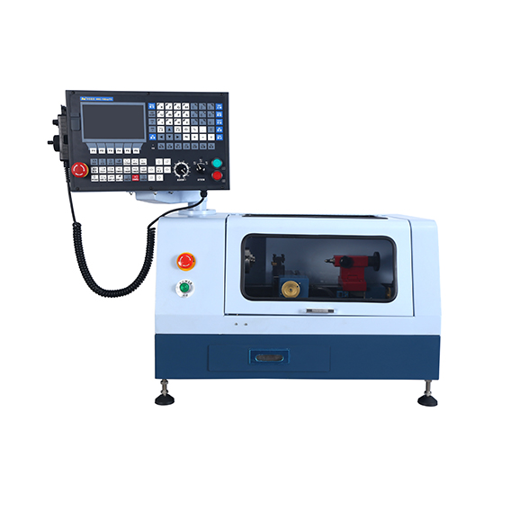
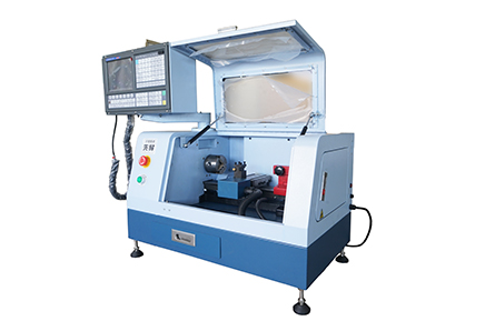
▸High performance 2 axis Lathe CNC controller.| ▸8 inches color screen, interface can be made of parameter selection in both Chinese and English.| ▸The standard spec includes MPG hand wheel.| ▸Selection of high -quality casting materials, more compact, High strength guide way.| ▸Automatic 4 positions tool post.| ▸Controller auto stop work when door open.| ▸High quality 2 axis AC Servor Motor.| ▸USB and RS232 port, DNC function of USB.| ▸Control speed of G code.| ▸Best choice for DIY or Hobby user and Education & Training CNC.|
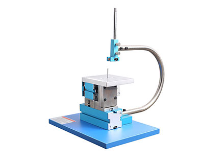
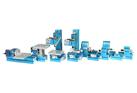
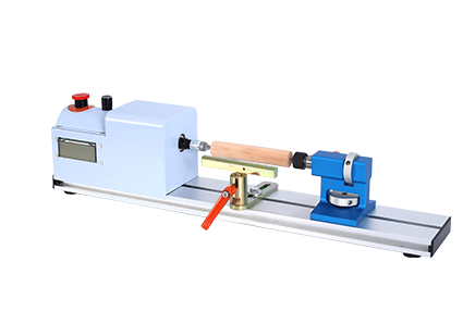
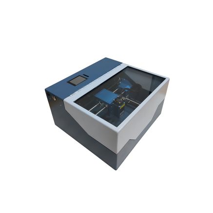
Metal Jigsaw | Metal woodturning Machine| Metal lathe Machine | Metal Milling Machine| Metal Drilling Machine| Metal Sanding Machine| Metal On-hand machine| Metal Drilling machine with dividing attachment


Xendoll has 22 years of experience in the production of small machine tools. We will help you choose the suitable machine and share our experience in CNC machining with you.
 Aug 29, 2025

 2337
2337
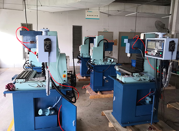
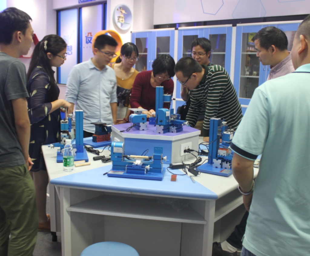
For educators, hobbyists, and future engineers in the STEM field, understanding the fundamentals of machinery is a cornerstone of learning. The mini lathe, a central tool in any hands-on STEM workshop, serves as a perfect, accessible model to explore these core engineering concepts. One of the most critical systems to understand is power transmission—the process that takes raw power from the motor and transforms it into the controlled, precise rotation of the workpiece and the movement of the cutting tool. Grasping this process is key to unlocking the full potential of a machine, especially when mastering variables like feed rate for precision work. At Xendoll Tools, we design our mini lathes not just as tools for creation, but as transparent teaching platforms for the next generation of innovators.
This article will break down the journey of power through a typical mini lathe, explaining each component's role in delivering controlled force to the cutting tool.

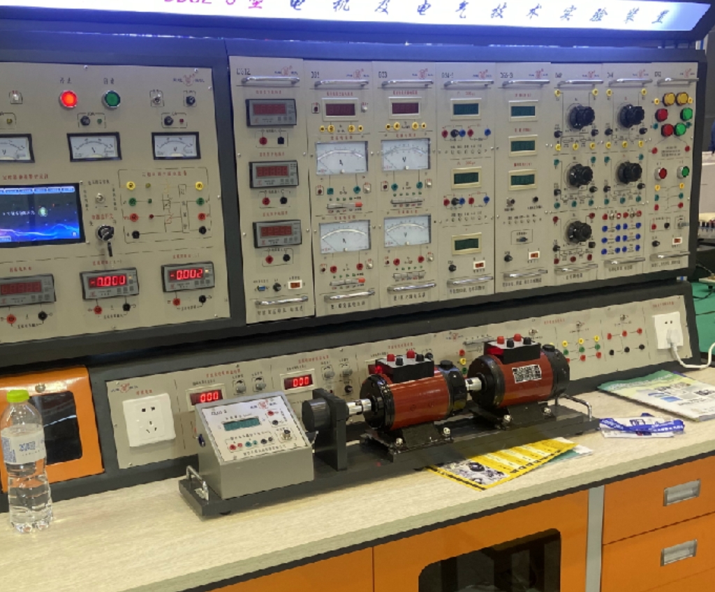
The entire process begins with the electric motor, the heart of the lathe. In mini lathes designed for education and hobbyists, this is typically a compact yet efficient DC or AC motor.
The Source: The Electric Motor
The motor generates rotational force (torque) at a high speed but relatively low torque. This initial power is not yet suitable for the direct demands of machining metal or wood; it needs to be moderated and strengthened. Our Xendoll mini lathes often feature variable speed motors, allowing students to safely experiment with how rotational speed affects the finish of a material—a fundamental lesson in machining.
The First Transfer: Belts and Pulleys
To make the motor's power usable, the first stage of transmission usually involves a belt and pulley system. The motor's shaft has a small pulley connected to it by a V-belt or timing belt. This belt drives a larger pulley on the input shaft of the lathe's headstock.
This setup is a perfect practical demonstration of mechanical advantage. The ratio between the small driver pulley and the larger driven pulley reduces the speed but increases the torque significantly. This is crucial for providing the necessary force to turn a workpiece without stalling. By changing the belt to different pulley grooves, students can physically alter this ratio, directly observing changes in spindle speed and power—a key concept in mechanical engineering.
The Gearbox: Modifying Speed and Torque (Optional)
Some more advanced mini lathes include a simple gearbox within the headstock. Gears provide a more robust and positive drive compared to belts. By engaging different sized gears, the transmission ratio can be changed, offering a wider range of spindle speeds and torque settings. This allows educators to teach about gear ratios, a fundamental topic in physics and mechanical design.
Understanding how the spindle rotates is only half the story. The true magic of precision machining lies in how the cutting tool moves. This is where the concept of feed rate is born.
The transmission path splits here. While the main spindle continues to turn the workpiece, a portion of the rotation is diverted to drive the carriage that holds the cutting tool. This is typically achieved through a leadscrew or a feed rod.
Leadscrew: A long, precision-threaded screw that runs the length of the lathe bed. When engaged, it rotates, and a nut on the carriage translates that rotation into precise linear movement.
Feed Rod: Often used in conjunction with a gear train, it provides the motion for power feeding the tool along the bed.
The feed rate—the speed at which the cutting tool advances along the workpiece—is directly determined by the transmission system. It is a function of the spindle speed and the ratio of the gears connecting the spindle to the leadscrew. A higher ratio means the tool moves a greater distance per revolution of the spindle, resulting in a higher feed rate. Teaching students how to calculate and set the feed rate is a critical hands-on lesson in precision, surface finish, and material removal rates. Too high a feed rate can cause a rough finish or tool breakage, while too low can be inefficient. Our mini lathes provide clear gear charts and intuitive controls to make learning this relationship safe and engaging.
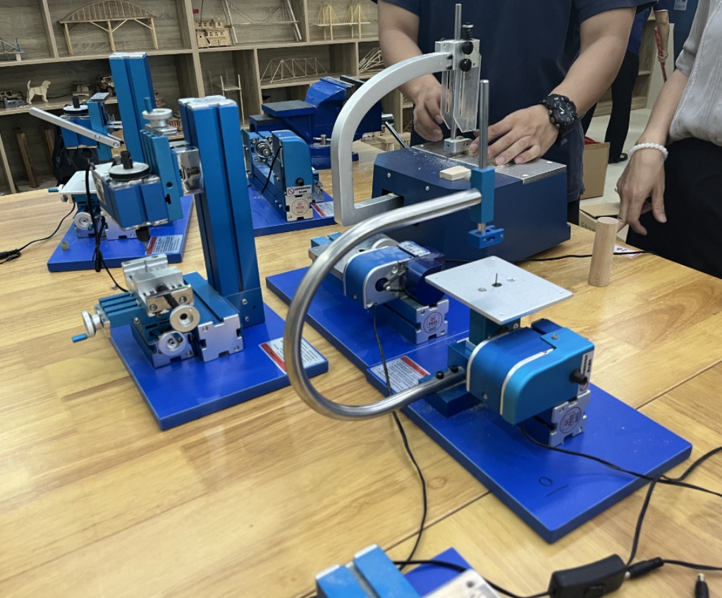
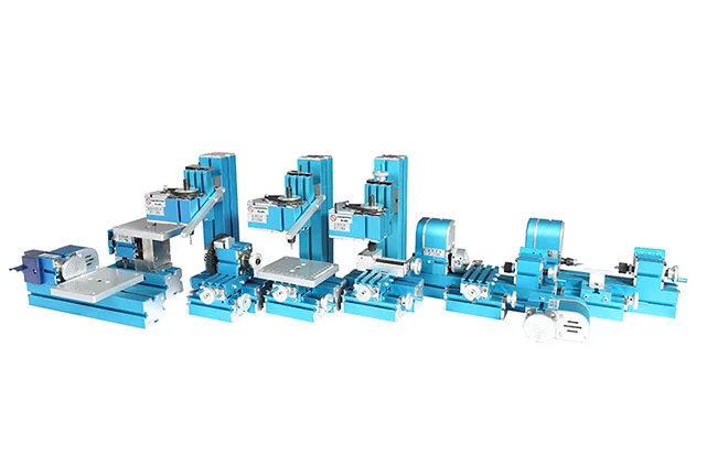
What makes a mini lathe for STEM education truly effective is the visibility of these components. Unlike large industrial machines with enclosed systems, educational mini lathes often have exposed headstocks and gear trains. This allows instructors and students to literally see the gears turning, the belts driving, and the leadscrew rotating, providing an invaluable visual aid that turns abstract theory into tangible reality.

The power transmission system of a lathe is a elegant dance of physics and engineering. From the motor's spin to the precise advance of the cutting tool governed by the feed rate, every step is a teachable moment. For a machining enthusiast, it's the key to unlocking precision. For an educational equipment distributor, it represents a powerful teaching tool. And for a overseas machinery dealer, it's a feature set that adds immense value.
At Xendoll Tools, we engineer our mini lathes with this educational philosophy at their core. We believe that by providing tools that demystify complex mechanics, we are empowering teachers and inspiring students to learn, create, and build the future.
Ready to bring these lessons into your classroom or workshop? Explore our range of educational mini lathes at xendolltools.com and see how Xendoll Tools can power your STEM journey.


 Show all our samples
Provide you with a free quote
Answer all the questions you may have
Guided installation and other options
Show all our samples
Provide you with a free quote
Answer all the questions you may have
Guided installation and other options